
Our equipment posts cover the making, modification and use of observatories, telescopes and equipment. Select the posts for more information on the topics.
Large Telescopes
The Society and its members possess a notable range of astronomical equipment, much of it home made. A number of the these instruments have been constructed by John Wall who is internationally known as a telescope maker and is the inventor of the ‘Crayford Eyepiece Mount‘ which has found favour all over the world.
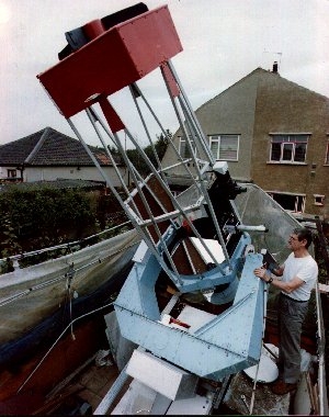
32″ telescope designed and built by John Wall
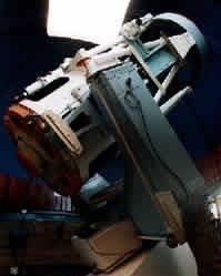
24″ telescope designed and built by John Wall
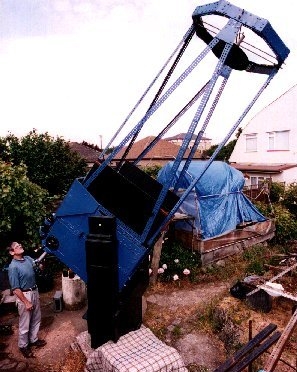
42″ telescope designed and built by John Wall
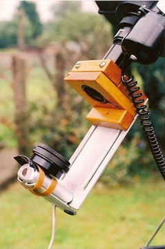
Variable Barlow
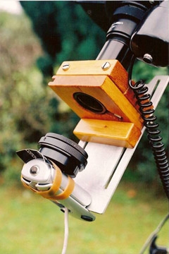
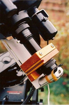
Variable Barlow Adapter for a Webcam
Changing the distance of an eyepiece or other sensor such as a webcam or DSLR changes the effective power (magnification) Andy Barber has made such a set-up for planetary imaging with a Phillips Toucam.
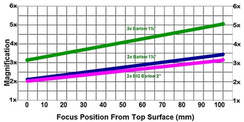
The effective focal length achieved will depend on the Barlow used and the distance from the Barlow to the imaging surface. These are calculated and displayed in the following graph.
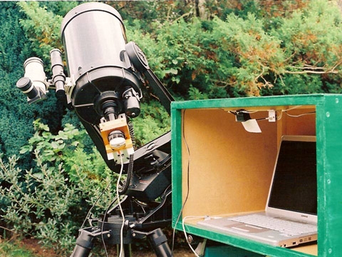
Andy’s set-up including the box that protects the Laptop from the damp.
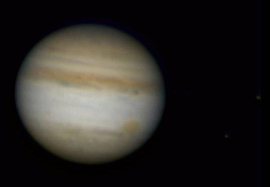
Image of Jupiter taken with a variable Barlow and Philips ToUcam in 2010
DIY Finderscope
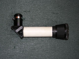
ATM Finderscope
A finderscope is an essential accessory for your telescope, if you don’t have one, or your finderscope uses an objective less than 50mm in diameter you might consider making one, this is a satisfying accessory to make and doesn’t require any real skill or optical knowledge.
I had a spare pair of binoculars that were out of collimation so of no real use, so I turned the objectives into a finderscope, the first I reused the objective and the focusable binocular eyepiece to make a ‘straight through’ finder with a 10x magnification and the second (shown here) used a broken star diagonal I was given (repaired but only for small loads) and the binocular objective.
The tube is made from a kitchen waste pipe and covered with as astronomical image from Hubble to make it look nice!
Completed Finder
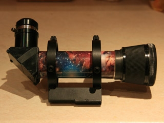
With mount and covering
A Battery-free Electric Focuser
A Battery Free Electric Focuser
Building an electric control for your focuser can help you achieve focus easier & quicker. With an electric control focuser, there is no need to touch the telescope and so you don’t induce telescope wobble, which in turn, speeds up the task of focusing. You can buy electric focusers but they are expensive and can be difficult to mount (especially on refractors). This simple idea, is neat, easy to implement with parts bought from Maplin’s and despite being an electric focuser, it doesn’t use batteries!!!!!!
Time Delay Integration a.k.a Drift Scanning
What is Drift Scanning?
If you try to take an image on an un-driven mount the stars will trail as the Earth rotates. Now imagine a star on a CCD, it will move from pixel to pixel producing a line rather than a point source. Now if we could move the image on the CCD at the same rate as the star is moving across it, we would be able to keep the star as a point source on the image even though it is moving across the CCD. The total time of the exposure would be the time it takes for the star to cross the CCD.
Drift scanning employs a special feature of some CCD cameras, such as the SBIG ST-7XME CCD camera. Data on these CCD’s can be read out one line at a time, and when this is done, the the whole image is shifted, so as the bottom line is read out to the computer, all the other lines move down. If the CCD is rotated correctly it can be read out in the same direction a star travels across it, and if it is read out at the same speed as a star travels across the chip from pixel to pixel we will have pin point stars.
Why Bother
This seems a lot of bother when you could simply drive your mount, so why do it? Well by employing this method it is possible to produce very long images like the one below.
Software
Two pieces of software are available for drift scanning;
Maxim DL (commercial ~$199 to $665)
WinScan 2.33 (freeware) www.driftscan.com
Pros and Cons
The Pros
- The set-up does not have to be driven
- Is simple (?)(!)
- Wide field shots can be taken
- Polar alignment is not required
- Little equipment is needed:CCD camera Telescope / Long Lens
- Tripod
- Laptop
The Cons:
- Pointing, because the image will be a strip of the sky so when you start you won’t be on your target(s)
- Obtaining accurate parallel/perpendicular alignment
- Focussing is a nightmare if not on a driven mount, but is achievable
Setting up the software
Only works with certain focal lengths
Differential trailing can be a problem
Viewing the images (they are large up to 32,000 pixels wide not many viewers will display them
Crayford Eyepiece Mount (Crayford Focuser)
Introduction
Designed and donated to the world by telescope maker and former member John Wall.
The design has two principle features:-
- Restriction of movement of the eyepiece focusing tube to one degree of motion – which is linear – and a secondary motion of rotation.
- The rapid interchange of eyepieces having different magnifications.
The restricted linear motion is achieved by mounting the eyepiece tube on rollers in a VEE formation using well known kinematic principles. This configuration eliminates side wobble and sticking, and the need to machine high precision bushings for the eyepiece tube in order to achieve accurate focusing action. Most CEM’s use this system only, especially in conjunction with motorised focusing for CCD work. The linear motion is achieved by using a smooth pinion, which bears onto the focusing tube under light pressure.

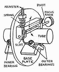
Classical CEM
Features: VEE block ball race support rollers for eyepiece tube; hinged bracket; actuating lever. The smooth pinion bears directly on the eyepiece tube – one of a suite of removable and interchangeable eyepieces.
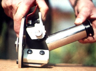
The quick release of the eyepiece tube: note the thumb tab action – this is an alternative to the sidelever.
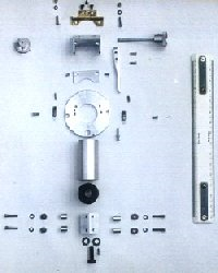
Exploded view of components to make a classical CEM. Scale rule is 300 mm.
The quick action release is the second and more important function of the CEM. By lifting a lever the focusing pinion is moved away from the eyepiece tube, in order to release it. This enables rapid eyepiece changing in the dark. The focusing pinion is mounted on a hinged, spring loaded, bracket. The application of this mode is most useful for visual observations and camera work.
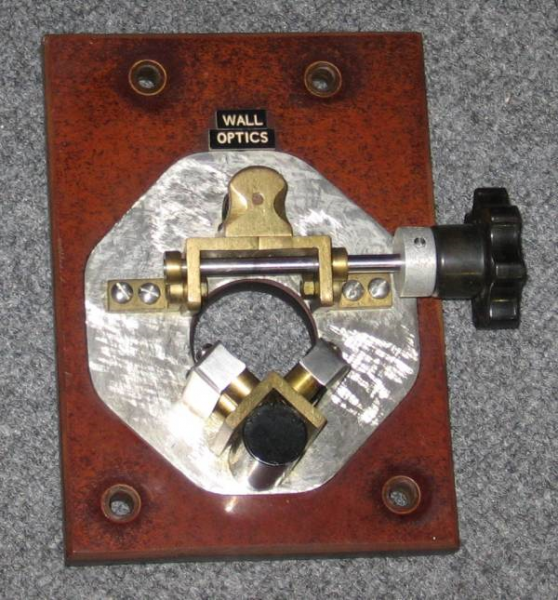
It’s Home!
The original Crayford Eyepiece Mount has returned home! It has been donated by creator and telescope maker John Wall and is now on display in its special Perspex box at the Pavilion. Below is a picture of it.
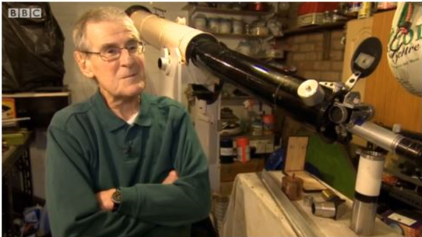
John Wall Interviewed by the BBC
No Results Found
The page you requested could not be found. Try refining your search, or use the navigation above to locate the post.